An intro to RGB pixel LEDs
Posted on Mon 27 November 2023 in Making
RGB LEDs, sometimes called pixels, are lots of fun. Who doesn't like blinky lights?! They're not hard to use, though there's enough complexity to make these LEDs seem a bit daunting. In this post, I'll go through the basics to get you started on your blinky fun.
Traditional LEDs display a single color. Bicolor and tricolor variations can show multiple colors. RGB LEDs, on the other hand, let you show any color in the rainbow (ignoring some color theory stuff that limits their actual gamut). Traditional LEDs need just the right polarity power to the appropriate pins in order to light up. RGB pixels require some sort of microcontroller to specify what color to show and to specify when to show it.
Addressable vs non-addressable
To be clear, in this article I'm talking about addressable pixels. With this type, the microcontroller can specify a different color for every LED in the set. There are also non-addressable LEDs, sometimes called analog LEDs. With those, you can display any color but all of the LEDs in the set will show the same color.
With non-addressable LEDs, a separate signal is fed to red, green, and blue LEDs (tiny ones, built into a single integrated circuit component). By varying the power sent to each, you can represent any color in the rainbow. But again, keep in mind that all the LEDs in the set will show the same color.
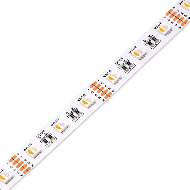
You can identify analog, non-addressable LEDs by their inputs -- if you see connectors for R, G, B, and a voltage (typically 12v), then you're dealing with a non-addressable LEDs set. As shown here, sometimes these strips also include a white channel (W) to give brighter, purer white output.
In contrast, addressable LEDs will have pins for voltage, ground, and data (or signal). Sometimes, an additional clock pin is used. Addressable LEDs come in 5v and 12v varieties, and sometimes even in other voltages. So, the typical inputs will be labeled +5, D, and GND; or +5, D, C, and GND. In and out matter. So, you will probably see labels like DI and DO for data in and data out. Sometimes, you'll just see an arrow on the strip. The arrow points to the out side. You must put your inputs into the in side or the strip will not light.
WS2812B vs APA102C vs ... oh my
You will see many different identifiers that describe the type of addressable LEDs. Most times, these are product numbers, such as WS2812B. Some vendors have assigned their own names, like neopixels or dotstar, which in my opinion just adds confusion.
In broad terms, all the addressable LEDs can be broken down into roughly two camps: 3-wire vs 4-wire. 3-wire pixels required power, data, and ground connections. Common examples are the WS2812B and SK6812. Those are 5-volt examples, though 12v versions, such as the WS2811 are also available. Adafruit calls their 5 volt, 3-wire pixels "neopixels" (SK6812).
4-wire pixels need power, data, clock, and ground connections. The most common are SK9822 and APA102C. Again, there are 5v and 12v versions. Adafruit calls their 5 volt, 4-wire pixels "dotstar" (SK9822). Because of the clock signal, 4-wire pixels can change colors more rapidly and more uniformly.
In essence, with 3-wire pixels, the data sent down the line is a series of values for each pixel in line. As the signal arrives at the IC, the chip "takes off" the value at the top of the list, lights up according to that signal, then passes the remaining signal down the line. Thus, each pixel in the strip lights up at a slight delay after the LEDs that precedes it. (The delay is barely noticeable on even the longest strips.)
With 4-wire pixels, again the data is sent as a series of values and each pixel takes off its value and passes the remainder down the line. However, the pixels don't show the new color value until the clock signal line switches. In this way, the pixels all change in unison. The real benefit of this technique is that you can more rapidly change colors since the timing is closely controlled by the clock signal.
While you can mix and match types controlled by a single microcontroller, it's easiest to stick with a single type for a given project.
More power!
Pixels draw a lot of power. For example, the WS2812B draws 50 milliamps per pixel at full brightness. That adds up. A strip of 30 pixels will draw as much as 1.5 amps. Your Arduino might run off some random phone charger but since the typical phone brick puts out 1-2 amps, you won't be driving too many pixels off of it. At the extreme, 5 meters of 144 pixel per meter strip will need as much as 36 amps at 5v! For that, you'll need a specialty power supply.
With longer strips, you'll also want to consider power injection. In addition to supplying power at the beginning of the strip, with power injection you supply the same voltage farther down the strip. For example, you might connect your power source to the +5 line every meter on a long strip.
You can buy high amperage power supplies off Amazon or other online retailers. Another handy way is to repurpose an old laptop power supply. They typically output some higher voltage, say 19 volts. You can use a DC to DC converter to step down the power to the voltage you need. Amazon, Adafruit, and others sell DC-DC step-down converters in various form factors.
Coming up
This post is getting too long so I'll end it here. In the next post, I'll cover wiring, connecting to your microcontroller, and show a basic sketch for displaying some colorful blinkies. I'm planning a third post in the series to cover the libraries -- FastLED in particular -- commonly used with pixels. Stay tuned!
